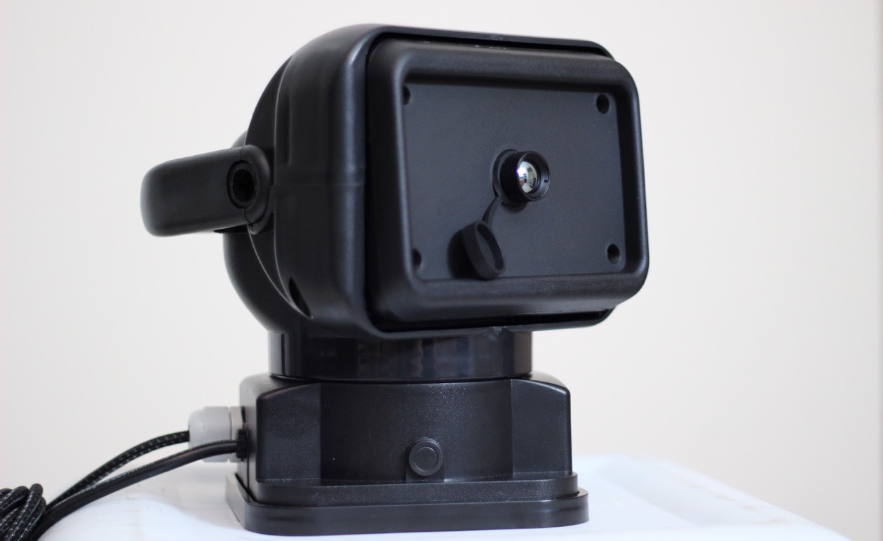
We recently reviewed the InfiRay Xinfrared T2 Pro thermal camera and found it is a great way to get into thermal imaging on a budget. I purchased this device specifically to scan for animals while driving. Normally the T2 Pro is attached to your phone which makes scanning while riding around somewhat difficult. However, this modification can turn this handheld device into a vehicle mounted thermal camera turret that can be viewed and controlled from inside the vehicle. The total cost including the Xinfrared T2 Pro thermal camera is about $500. If you already have the thermal camera, it only cost about $100 to turn it into a vehicle mounted turret.
What You Will Need to Create a Vehicle Mounted Thermal Camera Turret
Requirements:
- Thermal camera
- This guide uses InfiRay Xinfrared T2 pro but other cameras could work as well.
- Make sure to buy the correct version as they are different for Android and iOS.
- Android compatible Xinfrared T2 Pro on Amazon.
- iPhone/iOS compatible Xinfrared T2 Pro on Amazon.
- Motorized pan and tilt spotlight.
- Depending on the type of phone or tablet you want to use, a USB C or Lightning extension cable.
- Tools:
- Philips screwdriver.
- Hex screwdriver (or appropriate Allen keys).
- 2mm and 2.5mm hex bits.
- Step drill bit or anything to widen an existing hole.
The following are nice to have and make the finished product more professional, but are not necessary for it to function:
- 3D printer and heat-set 3mm nuts
- Cable gland
Warning! This camera turret is intended to be mounted on your vehicle only at VERY LOW speeds. This should only be mounted to your vehicle when necessary as the magnet isn’t that strong and could easily fall off if you are not careful.
Overview of the Vehicle Mounted Thermal Camera Project
If you are interested in the big picture and won’t have any trouble taking the light apart and putting it back together, here are the major steps you will need to take:
- Take the motorized light apart removing the LED circuit board.
- Route the USB or Lightning extension cable through the light body.
- Mount your thermal camera in the area where you removed the LEDs.
- 3D print or otherwise create a mounting bracket to hold the thermal camera in place.
- Reattach the necessary components of the light.
- Go out at night and find some wildlife!
Detailed Instructions on How to Disassemble the Vehicle Mounted Spotlight
Step 1 – Get Your Workspace and Tools Ready
- Make sure to keep track of all the parts that you remove
- I recommend writing down where the screws came from and keeping them in separate labeled piles
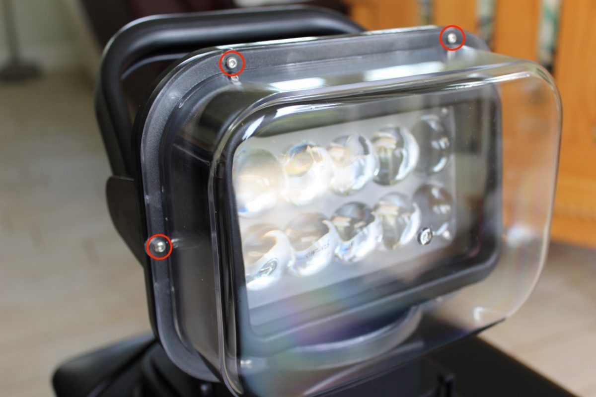
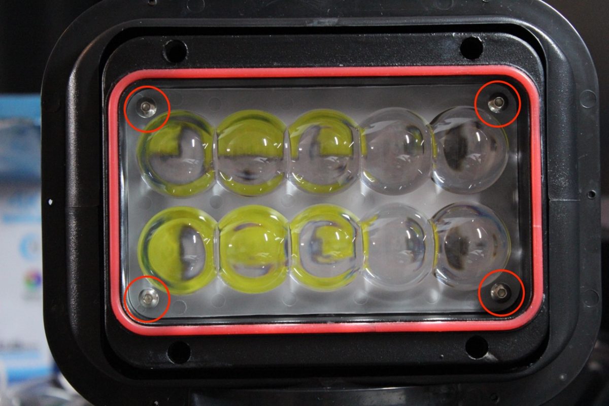
Step 2 – Remove Clear Plastic Cover
- Use a 2mm hex bit to unscrew 6 screws holding on clear plastic housing
- Remove plastic housing and remove the rubber gasket underneath
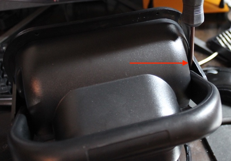
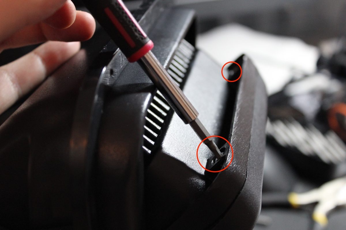
Step 3 – Remove Plastic Bracket and Handle
- Put the screwdriver in the area shown below – in between the handle and the plastic bracket holding the handle on. Gently pry this housing off on each side.
- Remove the black plastic bracket that held on the clear plastic cover.
- Now the handle should be easy to pry off on each side as well.
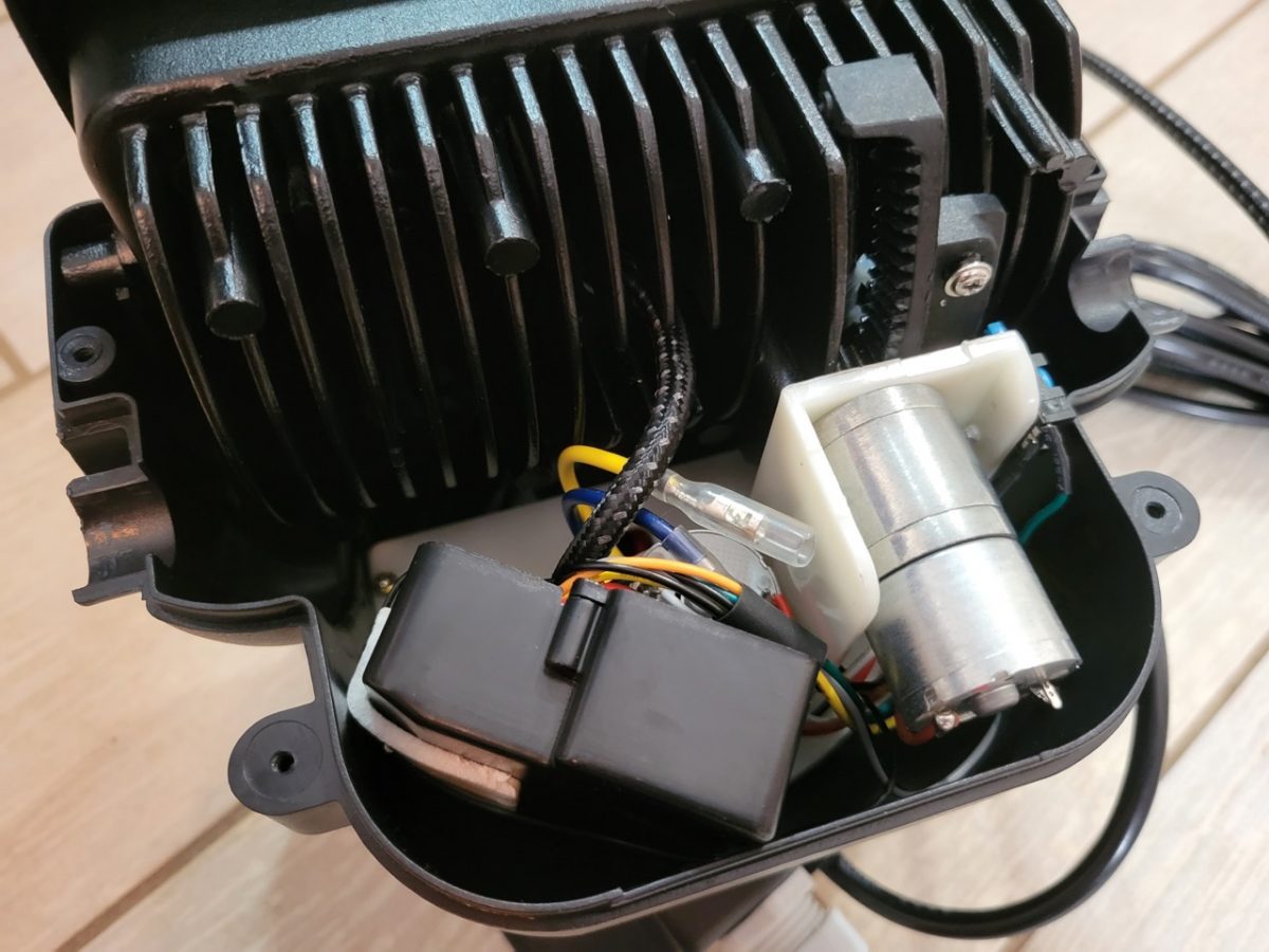
Step 4 – Remove the Top Cover
- Turn the unit upside-down to reveal 4 Philips screws that hold on the top cover.
- Unscrew them and remove the top cover to reveal the guts of the light.
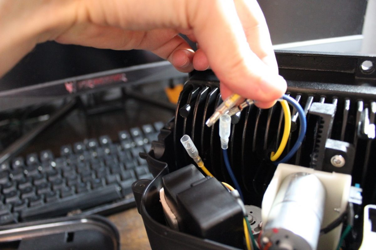
- You will see two power wires (yellow and blue) for the LED light.
- Make SURE the unit is unpowered (not plugged in) before pulling the connectors apart.
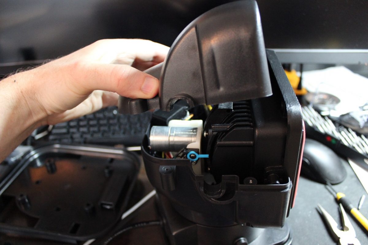
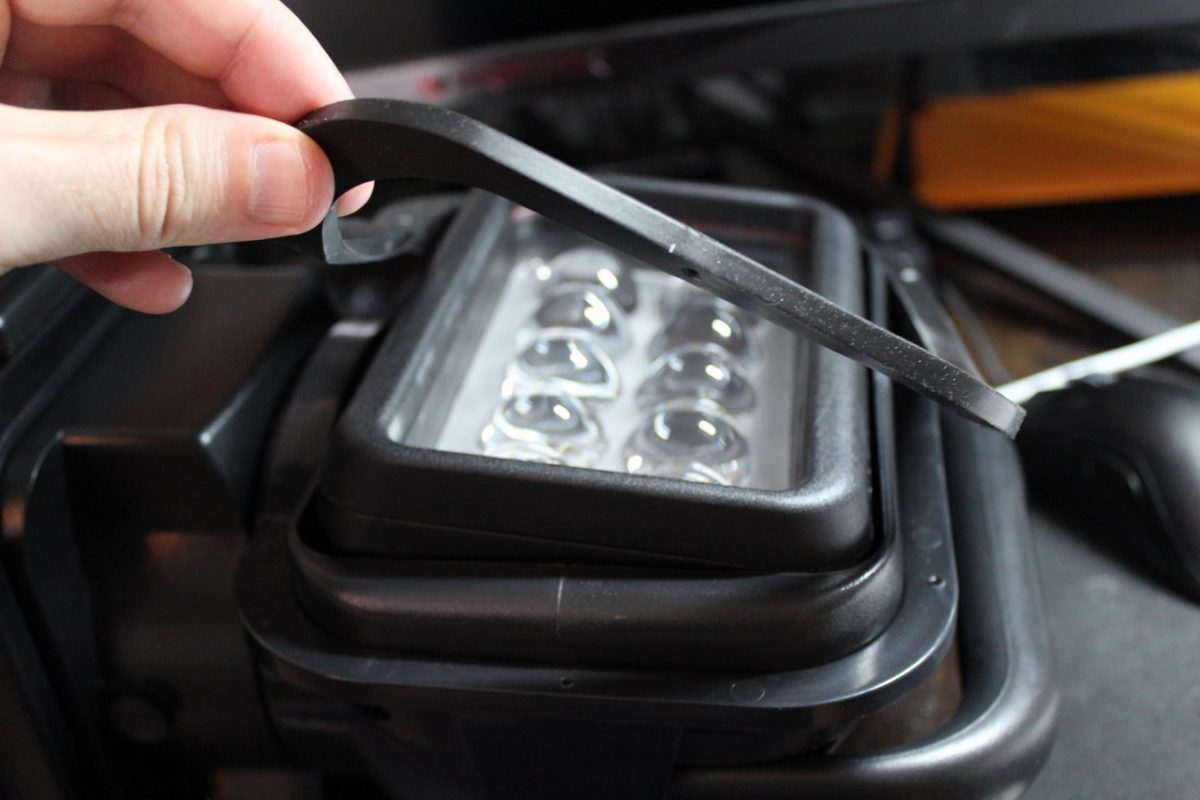
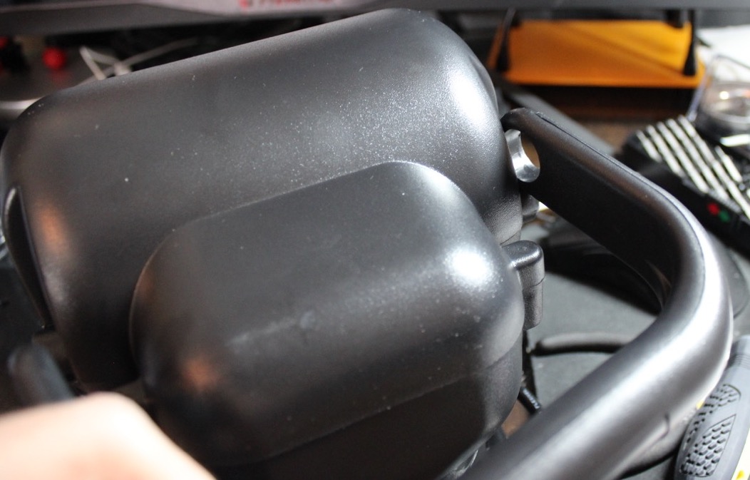
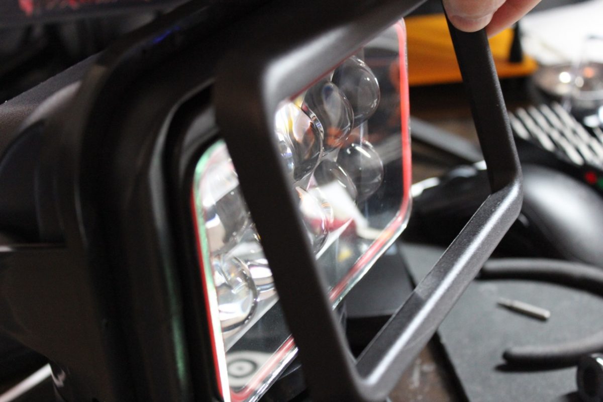
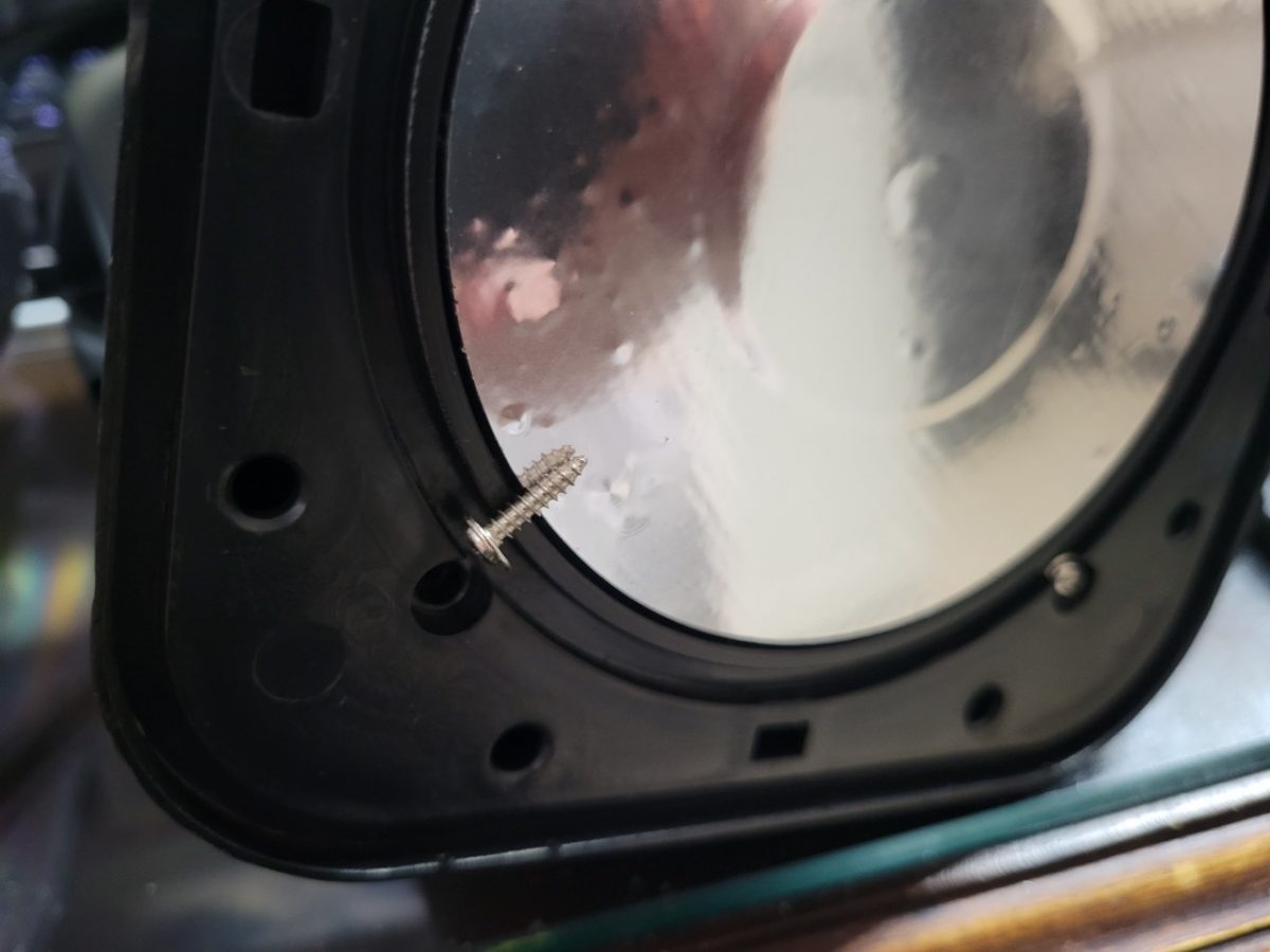
Step 5 – Remove the LED Tilt Assembly Bezel and Glass Cover
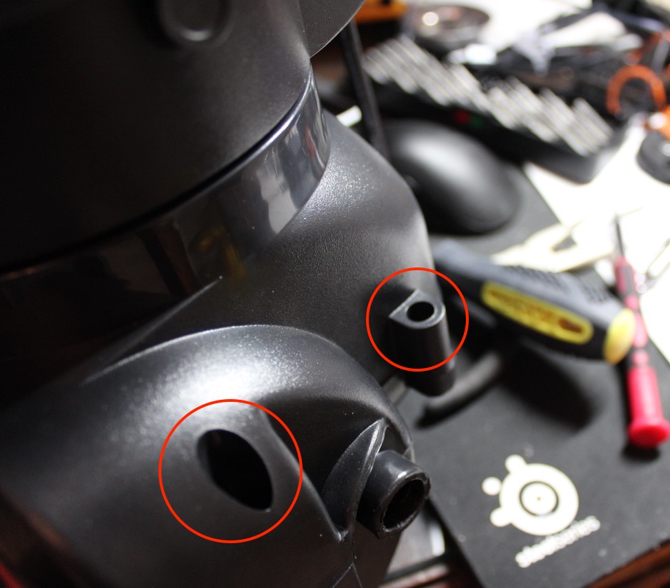
- Now the LED tilt assembly should be easy to access at the top. Remove the 2 hex screws (2.5mm bit) at the top of the tilt assembly.
- You may need to tilt the assembly in the upward direction to remove the 2 hex screws (2.5mm bit) at the bottom.
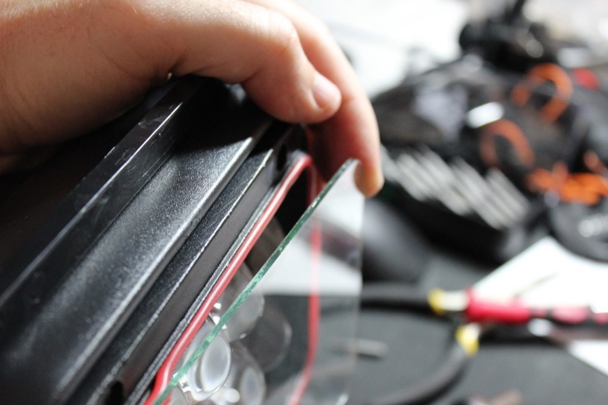
- Remove the black plastic bezel from around the glass.
- Carefully pull away the glass in front of the LEDs.
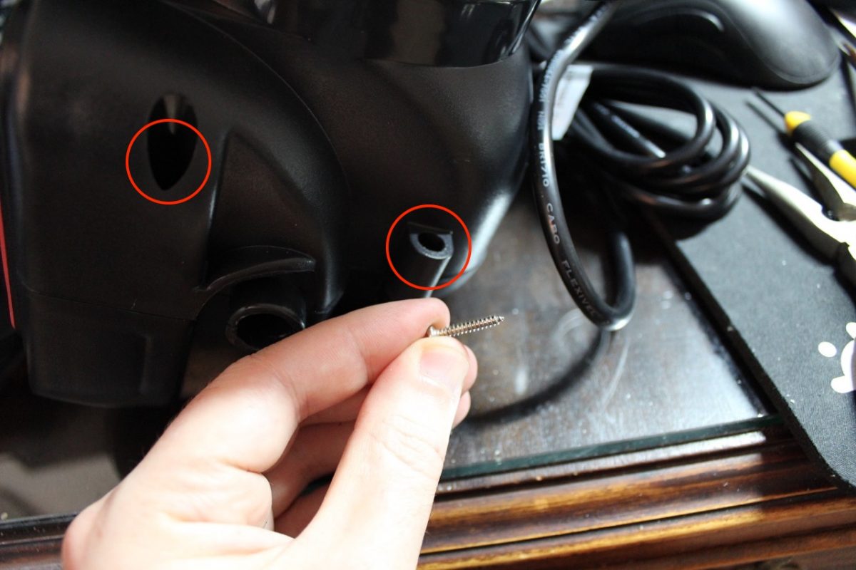
Step 6 – Remove the LEDs
- Remove 4 screws that hold in the diffuser plate with a 2.5mm hex bit.
- Remove diffuser plate to uncover the LED circuit board.
- Unscrew circuit board with a Philips screwdriver.
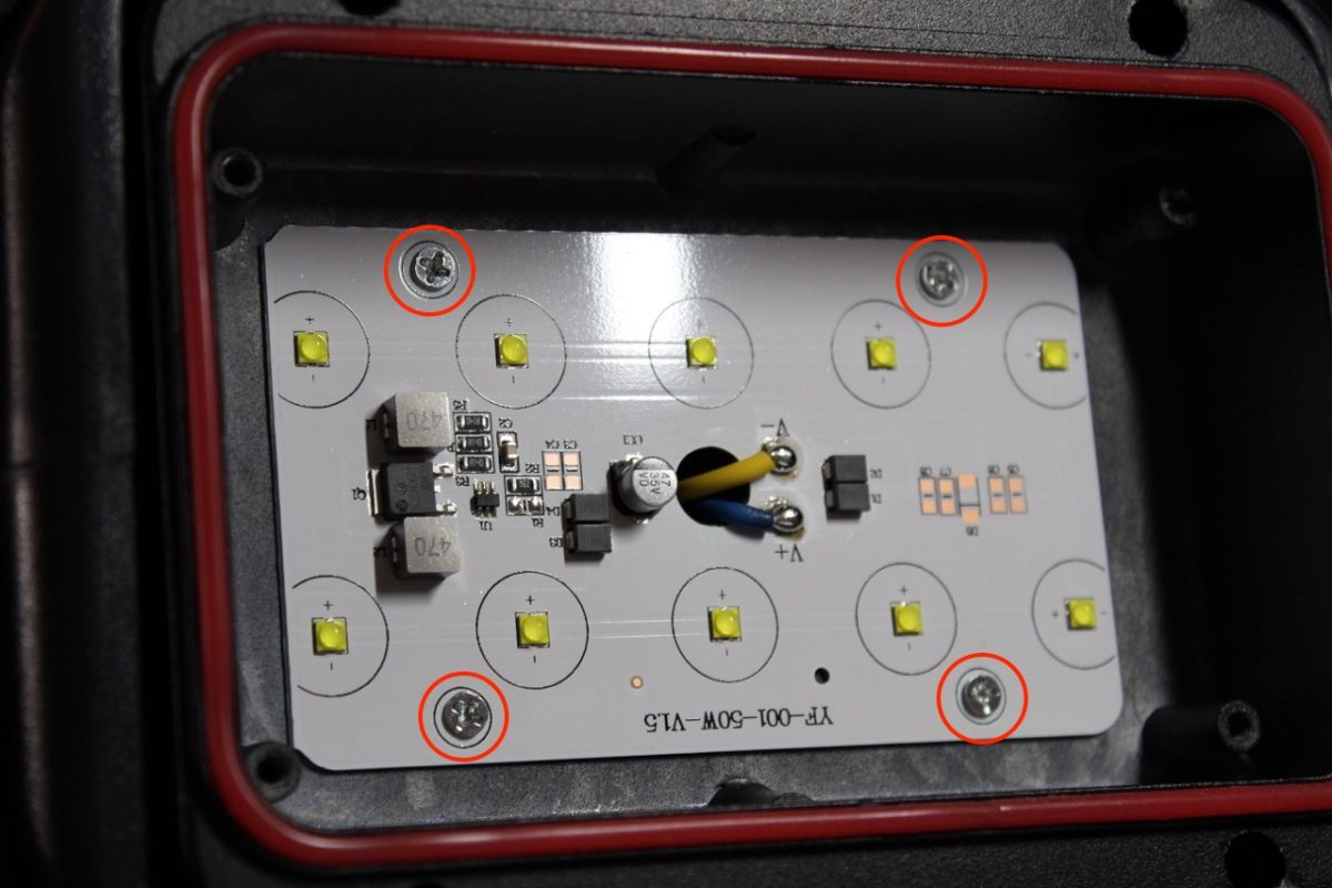
- The LED board may be stuck and require prying out because it has lot of thermal paste on the back to dissipate heat to the surrounding metal.
- Pull the circuit board away. Behind the circuit board you will see a hole where the wires are going through. There will be a rubber grommet protecting the wires that you can also remove.
Step 7 – Remove the Base and Magnet
- Next we need to remove the base and magnet. Turn the unit over and remove the rubber mat that is held in by friction. If you are having trouble just pry it off with a screwdriver.
- Removing the rubber mat will reveal 4 Philips head screws. Unscrew them to remove the base and magnet.
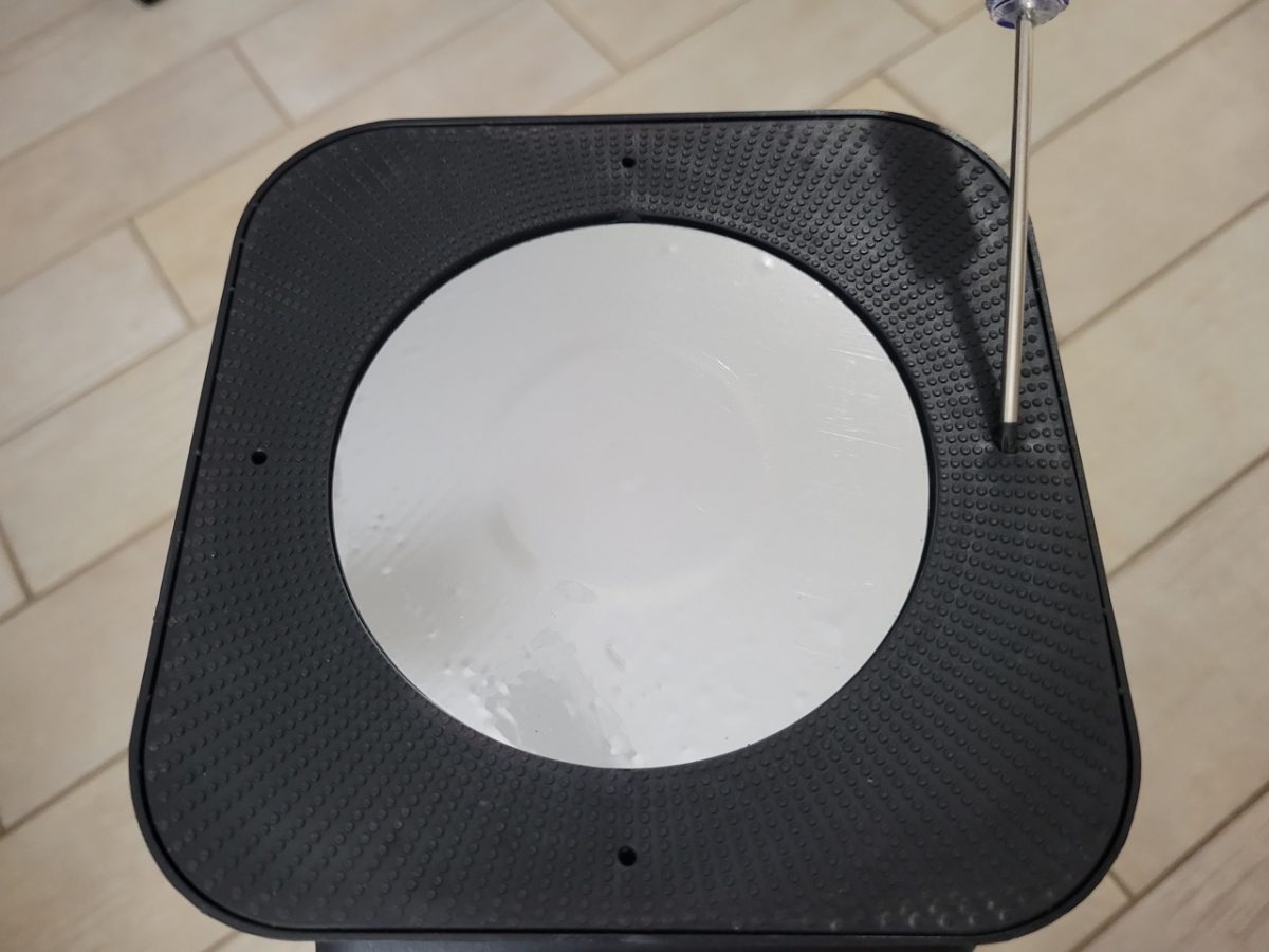
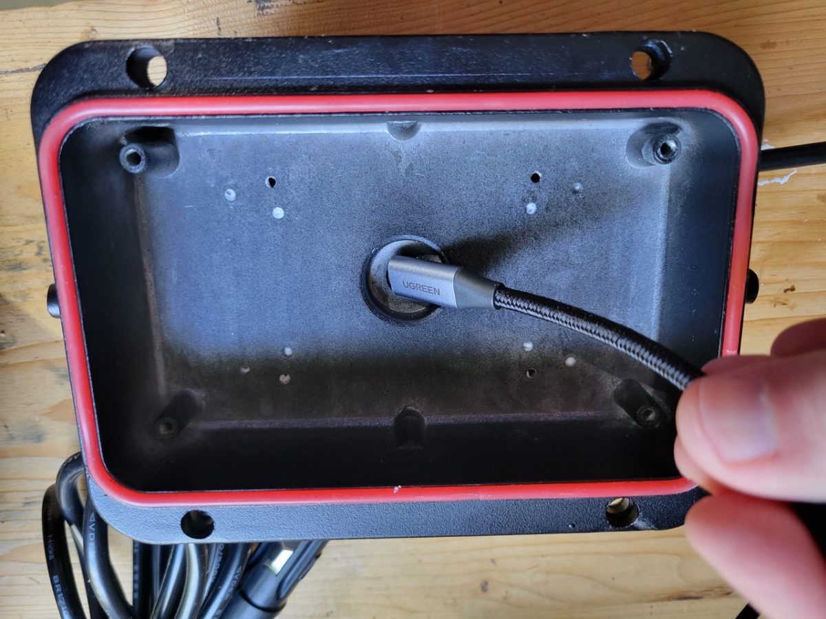
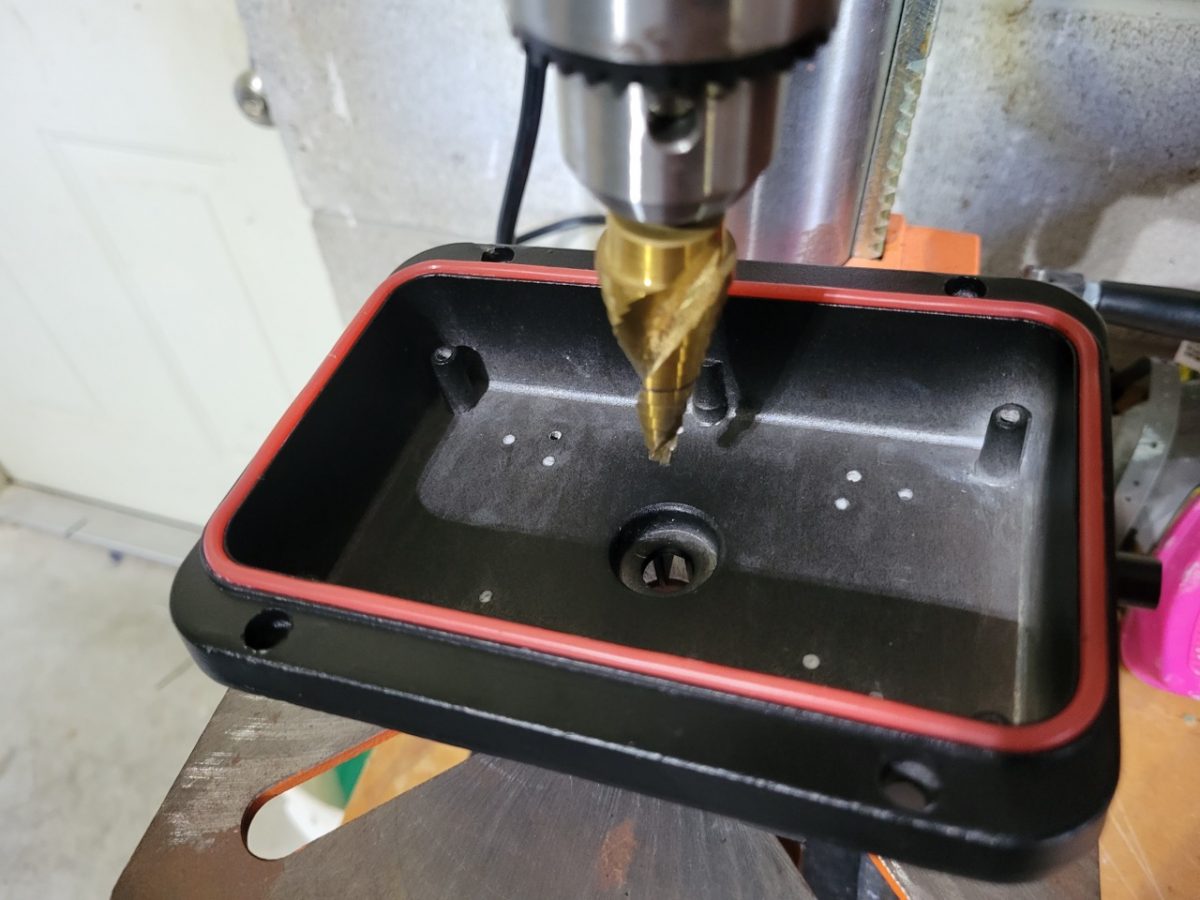
Step 8 – Drill Hole in Base for USB Cord
- Next drill a whole for your USB extension cord to go through the base.
- I had some cable glands handy so I added one of those, but if don’t have any, it is not a requirement.
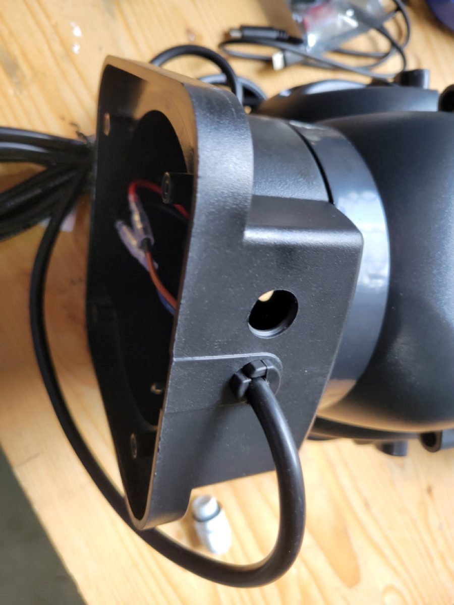
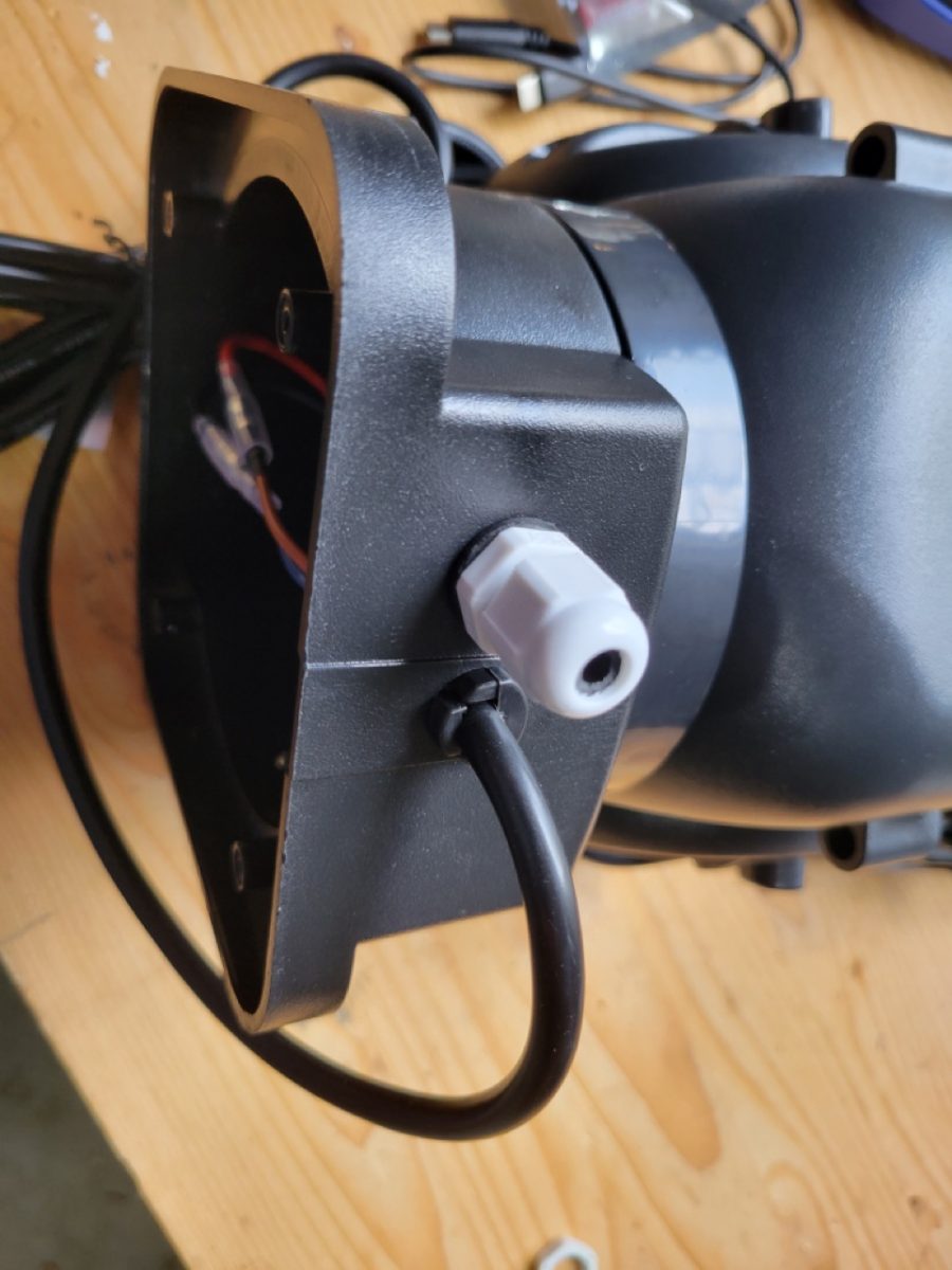
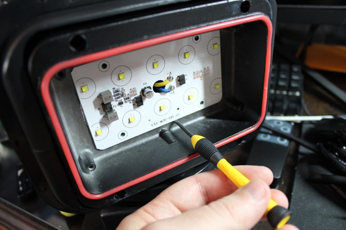
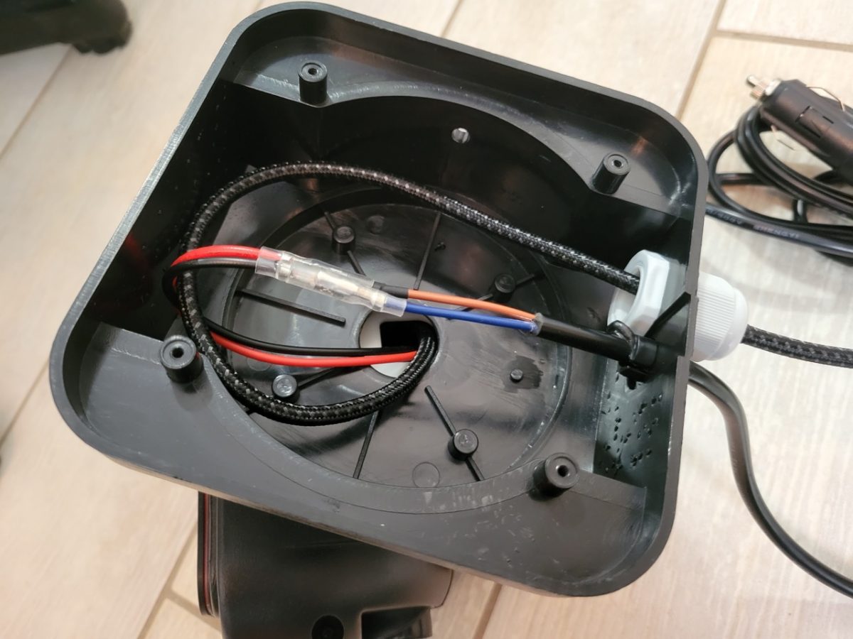
Step 9 – Pass through USB Extension Cord
- Go back to the tilt housing and check if your USB or Lightning extension will fit through the hole in the back.
- My USB extension wouldn’t quite fit, so I widened the hole with a step bit.
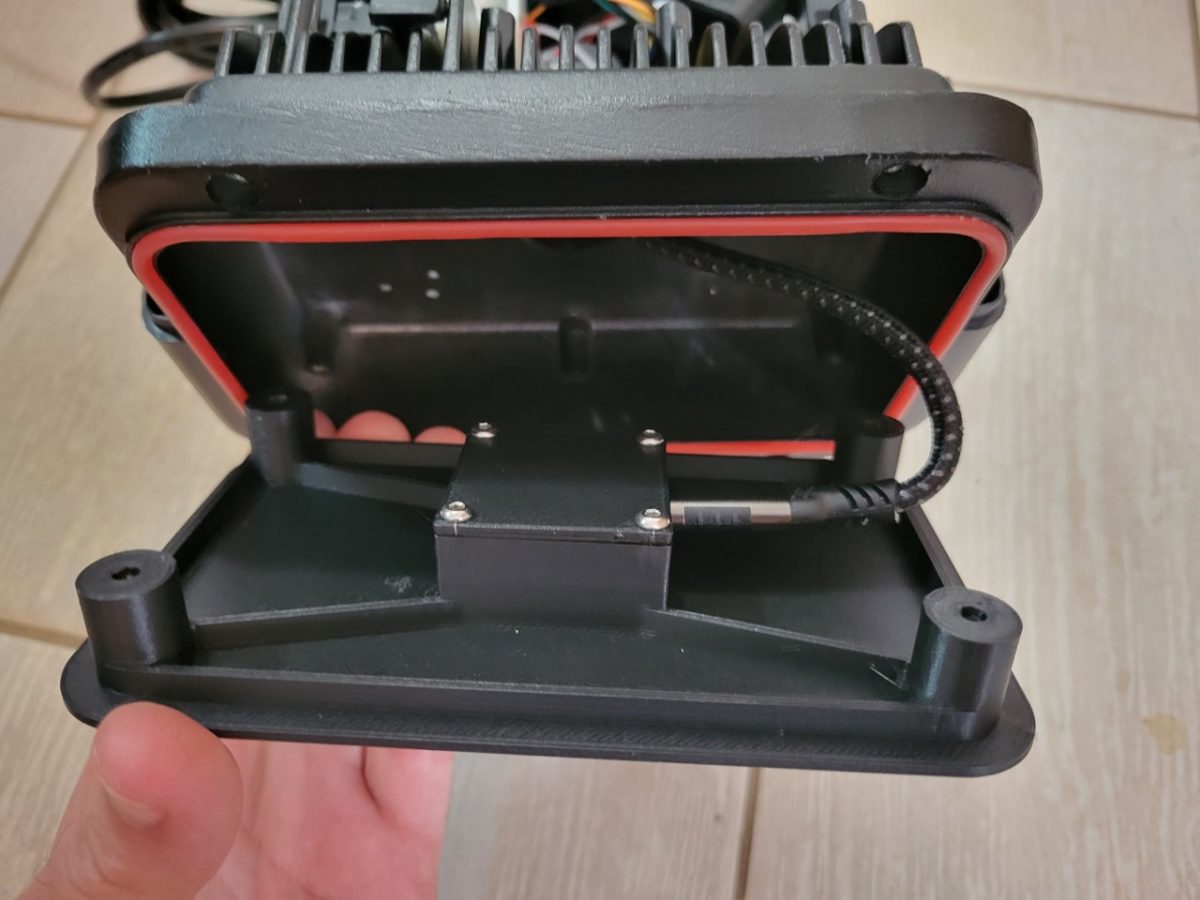
- To make this easier you can easily remove the entire tilt assembly by pulling it straight forward away from the motors.
- Start with the base and pass your USB extension through the base into the body making sure to leave slack in the base so that it doesn’t pull out of the camera when it is turned.
- Pass it though the tilt housing and then reattach the tilt housing to the main body.
Step 10 – 3D Print the Camera Housing or Create Your Own Bracket
- I already did the work of creating a printable 3D model that works with the InfiRay Xinfrared T2 Pro and the light linked above. You can download it here. It is meant to be used with 3mm heat-set nuts.
- If you have a different light or a different camera, you may need to make some adjustments to the model.
- Print the model without supports. Using a soldering iron or similar, press in the brass nuts so that they are flush with the top of the model.
- Place your camera into the printed piece. Use M3 screws to screw in the back cover that holds the camera in place.
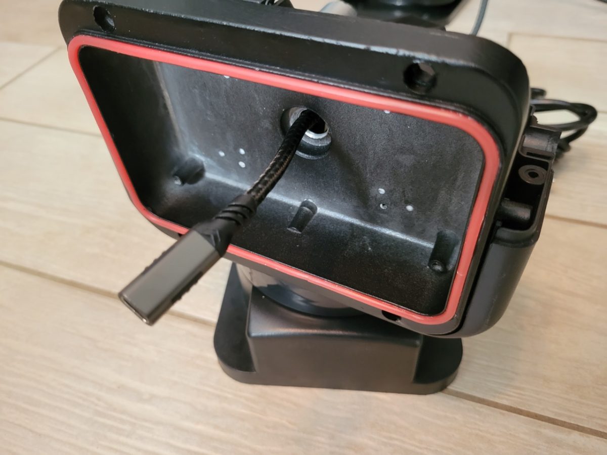
- Attach USB extension cable.
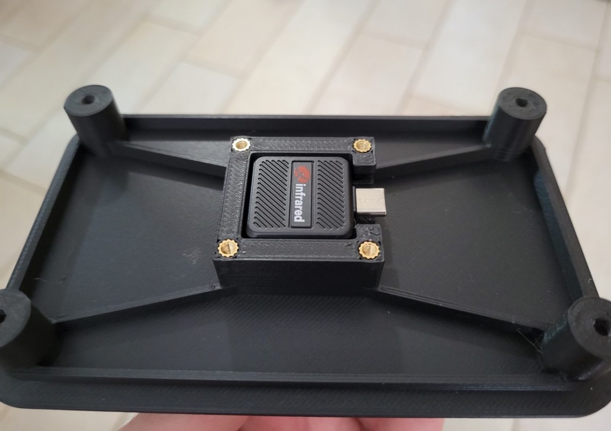
- Now get the original screws that held in the diffusion plate and use them to attach the printed camera bracket to the tilt assembly.
Step 11 – Reassemble the Necessary Components
- You don’t have to reassemble everything, so it is a little easier to put back together.
- If you removed the tilt assembly go ahead and reinstall it now.
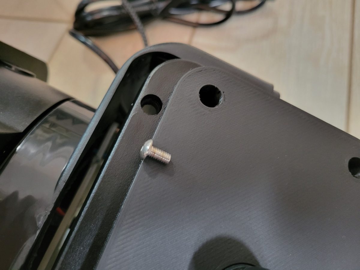
- Next, reattach the black bezel that you removed in step 5. This step isn’t strictly necessary as the 3D printed part is already screwed in, but it makes it look a little nicer.
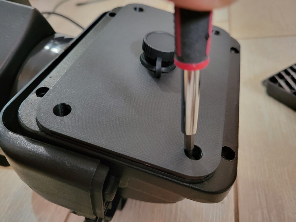
- Then reattach the base from step 7 and put the rubber mat back on the base.
- Reattach the top cover from step 4.
- Finally reattach the handle from step 3.
- You cannot add any of the other components like the clear plastic housing because it would block the thermal camera (thermal can’t see through glass or plastic).
Step 12 – Mount Thermal Camera Turret on Vehicle
- Mount the turret on top of your vehicle and route the cords inside.
- Plug in your phone or tablet and go find some wildlife!